Contact Info


News


- 90 Day Parts Warranty
- 5 Years Parts Limited Warranty
- State Licensed and Insured
- Factory Trained Technicians
- We Beat Any Written Estimate by 20%
- Well stocked truck ready to troubleshoot and fix you appliance problem on the spot.
- Free estimate if we do repairs
- 20% Off Labor for New Customers
10% Off for Seniors and War Veterans
- GAS RANGES
Before discussing these, we want to remind you that all safety organizations discourage do-it-yourself repairs to any home gas appliance. Because of the twin dangers of explosion and asphyxiation, this is a sensible precaution. But if you understand the operations of a gas stoves you can at least make certain it is being used in the most efficient manner and know when to call your gas company for service. In gas ranges the simplest and most common type of control device for the surface stove is a valve which has a plug between the manifold where the gas enters and the tube approaching the stove burner. At turn off position the hole between the two sections is closed. At stove high position it's completely open, simply a drilled passageway through file plug. As the stove burner is turned toward the lower setting, less and less of this passageway is exposed to limit the gas flow info the burner front the manifold. This, too, provides an infinite heat arrangement into file burner.
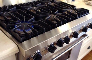
While the stove valve itself is simple enough, the flow of the gas broil through the mixing chamber to the burner is somewhat more complex. Primary air is admitted through a shutter near the orifice to mix with the gas on the way to the burner, and at the burner itself; the burner is designed to admit secondary air to make the flame more efficient and concentrated in the right places. The adjustment of the air shutter is quite important. Yellowness in the flame indicates an excess of carbon, usually caused by a lack of sufficient air. On the other hand, a hard flame which may even pull away from the burner ports is caused by too much air. The best way to set it is to open the shutter as far as it will go, giving a hard flame. Then turn the shutter in until the flame has a definite blue cone but a soft one with no traces of yellow. This should be the most efficient operating position for the gas burner.
Even with the correct amounts of gas and air mixture flowing to the burner, there still must be something to ignite it. Common practice in the past has been to have one or two standing pilots with tubes, called "Zip tubes" or "flash tubes," leading from the pilot to the burner. - LATCHING MECHANISMS
- When the lock handle of a mechanical latch is moved to lock, a latch finger moves from the top oven frame. The latch finger engages a slot in the top inner face of the oven door, pulling the door
and fiberglass seal against the oven front frame and sealing the door. The latch mechanism and lock switch are accessible by removing the handle knob and raising the range top. The latch switch
serves two purposes. At about 575 to 600 degrees, a bimetal moves a lock pin within the latching mechanism and effectively "jams" it. The lever can't be moved again until temperatures subside. At the
same time a set of contacts close within the switch and turn on the Locked indicator light. Since the latch switch operates by conducted heat, it must make good contact with the top of the oven liner
when it's replaced or repaired. With this type of latch, an actuating rod extends from the handle through the rear of the range, actuating interlock switches which insure that the range is in the
Locked position before cleaning circuitry is energized. These switches are serviceable from the back of the range. Elongated mounting holes allow adjustment of the switches. Adjustment of latch
finger is accomplished by removing E clip and turning threaded portion of rod. In case the mechanism malfunctions, the finger may be released by removing clip after oven has cooled. Pilot is
accessible after removing cover plate.
General Electric ranges incorporate an electrical solenoid into the mechanism which must be energized by a push button switch before the handle can be moved. At temperatures above 550 degrees, a thermal switch completes circuitry to the Lock light and the solenoid is inoperative even though the latch release button is depressed. The thermal switch closes, restoring the circuit to the solenoid, when temperatures are down to normal levels. The electrical latch systems have no latch handles. A latch finger engages a slot in the oven door just as it does in the mechanical latch, except that a rotisserie-like motor operates the latch finger through a rod linkage. This motor, located in the rear of the range, turns a cam that connects to the latch rod. The cam also actuates two switches, which act as limit switches for the motor, stopping it at the correct positions and providing circuitry to the lock light and oven temperature control. This mechanical latch mechanism engages door when latch lever is moved to locked position as shown. Jam pin is attached to bimetallic disk; it raises and jams mechanism in locked position as temperatures pass 550-degree mark. Pin should be .015 inch below surface of bracket at room temperatures. Be sure that bimetal on underside has good contact with top of oven body and that no insulation separates the two surfaces. Mechanical latch also has interlock switches to control clean cycle. Spring-loaded rod from latch mechanism actuates switch assembly. Be sure the range is unplugged before exposing wiring connections. Actuating mechanism of electric latch is this rotisserie-like motor mounted at rear of range. Motor-driven cam moves latch finger, actuating rod, and switches. Switch acts as a limit to start and stop motor at correct position, also completes the circuit to controls to prevent use of clean cycle unless door is latched. Door switch must be closed before motor will operate. Capacitor helps prevent TV interference when motor is running. Latch-limit switches are easily tested for continuity by removing lead, connecting VOM to terminals, and actuating plunger manually. Cam may also be rotated manually to check adjustment of switches. Meter should read zero ohms resistance with contacts closed. Naturally, when food soils are burned away in oven some smoke and odor must be present an objectionable factor it' something isn't added to remedy it. That something is an in the screen which is coated with platinum and palladium and then oxidized. It's called file smoke eliminator. The coated screen acts as a catalyst which causes smoke to burn at lower temperatures. Some manufacturers simply place the screen in the oven vent at the top of the oven. Others use an enclosed sheath type element or an open element encased in ceramic surrounding the platinum-palladium screen, giving an "afterburner" effect. These work amazingly well, but it is possible to overload them with heavy soils and greases with resultant smoking another good reason for removing major spillovers before cleaning.